
Measure once, build once
Every custom driveshaft is built to your measurements, so an accurate number is the most important part of the order. Aim to be within about 1/8 inch. If you're unsure about anything, take photos and text them to us before you order.
Step by step
Set the vehicle at ride height
Park on level ground with the full weight on the suspension, either on the ground or on a drive-on lift. Don't measure with the axle hanging, because suspension droop changes the length.
Identify the yoke at each end
Note whether the transmission or transfer case end uses a slip yoke that slides into the tailhousing, or a bolt-on fixed flange or yoke. Do the same at the axle pinion.
Measure a slip yoke shaft
With the old shaft removed, measure from the face of the transmission tailhousing seal to the center of the rear u-joint at the pinion yoke. We calculate the correct slip yoke engagement from there.
Measure a fixed-yoke shaft
If both ends bolt on, measure from the center of one u-joint to the center of the other, or flange face to flange face for flange-mounted shafts.
Record u-joint series and splines
Write down the u-joint series (for example 1310, 1350, 1410, 1610 or SPL170) or measure the cap diameter and span with calipers. Note the transmission or transfer case model and the output spline count.
Send it to us
Fill in the worksheet for your layout (below), then call or text (572) 568-1838 with it plus the measurements, photos of both ends, your year/make/model, horsepower and use, or submit the order form.
4x4 and long-travel shafts
For a spline-and-slip 4x4 shaft, also give us the length at full droop and at full compression if you can. That lets us make sure the slip has enough travel and never bottoms out or pulls apart.
Two-piece driveshafts
Measure each section separately and include the center support bearing position: the two-piece worksheets below show exactly where. Or bring in the old shaft and we'll take the measurements from it.
Measuring worksheets for every driveshaft layout
Find your layout below, print its worksheet, fill it in at the vehicle, and text us a photo. "New slip yoke" means we supply the slip yoke; "your slip yoke" means we reuse the one you have. Not sure which you have? Text us a photo of each end.
Download all 15 worksheets + u-joint chart (PDF)
Which worksheet do I need?
| Front end (transmission or transfer case) | One-piece to pinion yoke | One-piece to pinion flange | Two-piece to pinion yoke | Two-piece to pinion flange |
|---|---|---|---|---|
| New slip yoke (we supply it) | M1-1 | M1-4 | M2-1 | M2-3 |
| Your slip yoke (we reuse it) | M1-2 | M1-5 | M2-2 | M2-4 |
| Bolt-on (fixed) yoke | M1-3 | - | M2-5 | - |
| Transmission or transfer case flange | M1-6 | M1-7 | M2-7 | M2-6 |
Early GM X-frame car with an inline carrier bearing? Use M2-8. Bolt-on yokes at both ends only come with a pinion yoke, so the flange cells are blank.
One-piece driveshafts
M1-1
One-piece: new slip yoke to pinion yoke
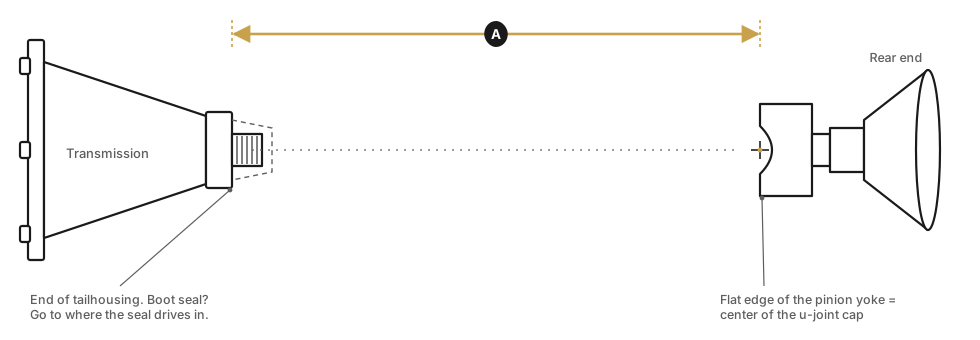
- A · Overall length: From the end of the transmission tailhousing (where the seal seats) to the flat edge of the pinion yoke (the centerline of the u-joint cap).
M1-2
One-piece: your slip yoke to pinion yoke
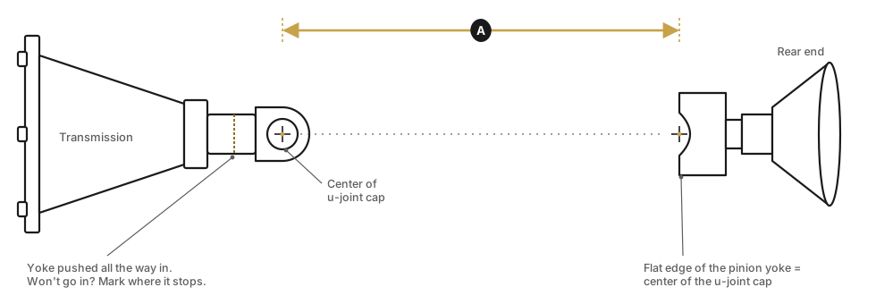
- A · Overall length: From the center of the u-joint cap in your slip yoke, pushed all the way into the transmission to the flat edge of the pinion yoke (the centerline of the u-joint cap).
M1-3
One-piece: bolt-on yokes at both ends
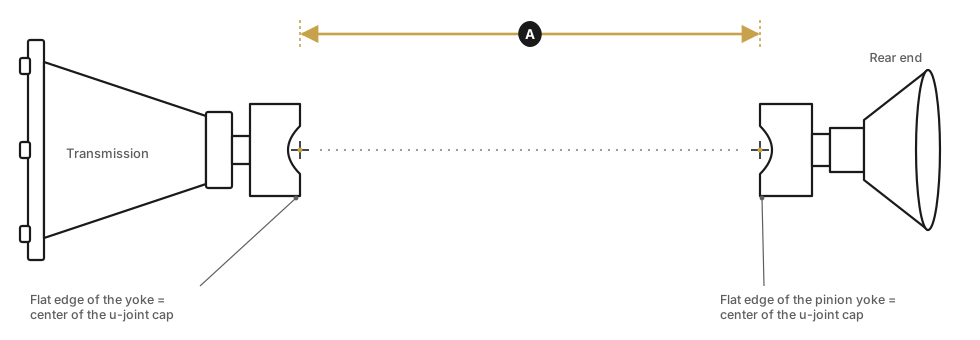
- A · Overall length: From the flat edge of the transmission yoke (the centerline of the u-joint cap) to the flat edge of the pinion yoke (the centerline of the u-joint cap). Flat edge to flat edge is the same as center to center of the u-joint caps.
M1-4
One-piece: new slip yoke to pinion flange
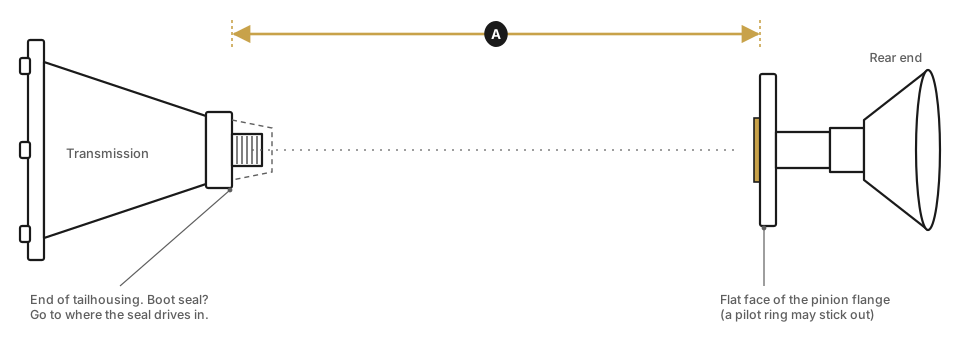
- A · Overall length: From the end of the transmission tailhousing (where the seal seats) to the flat face of the pinion flange.
M1-5
One-piece: your slip yoke to pinion flange
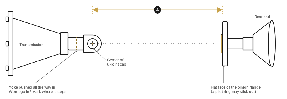
- A · Overall length: From the center of the u-joint cap in your slip yoke, pushed all the way into the transmission to the flat face of the pinion flange.
M1-6
One-piece: transmission flange to pinion yoke
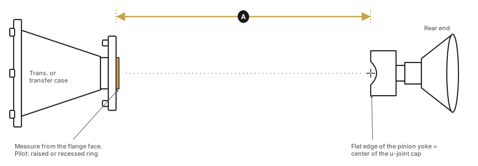
- A · Overall length: From the face of the transmission or transfer case flange to the flat edge of the pinion yoke (the centerline of the u-joint cap).
M1-7
One-piece: transmission flange to pinion flange
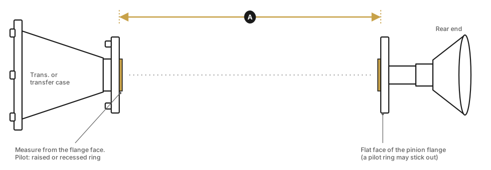
- A · Overall length: From the face of the transmission or transfer case flange to the flat face of the pinion flange.
Two-piece driveshafts (with a carrier bearing)
M2-1
Two-piece: new slip yoke to pinion yoke
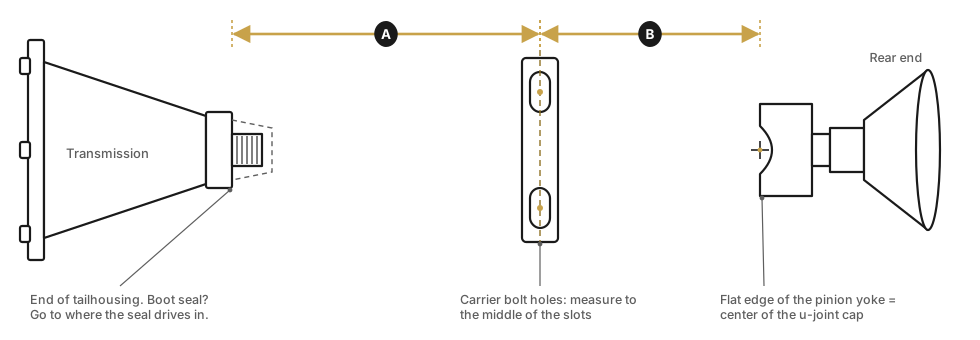
- A · Front length: From the end of the transmission tailhousing (where the seal seats) to the center of the carrier bearing bolt holes (middle of the slots).
- B · Rear length: From the center of the carrier bearing bolt holes (middle of the slots) to the flat edge of the pinion yoke (the centerline of the u-joint cap).
M2-2
Two-piece: your slip yoke to pinion yoke
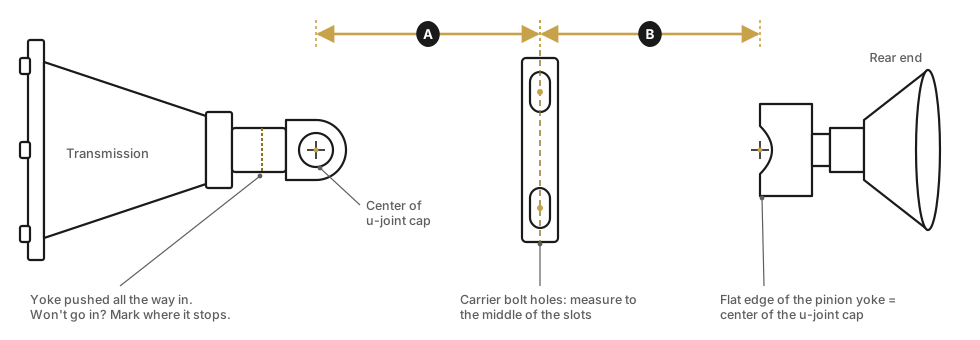
- A · Front length: From the center of the u-joint cap in your slip yoke, pushed all the way into the transmission to the center of the carrier bearing bolt holes (middle of the slots).
- B · Rear length: From the center of the carrier bearing bolt holes (middle of the slots) to the flat edge of the pinion yoke (the centerline of the u-joint cap).
M2-3
Two-piece: new slip yoke to pinion flange
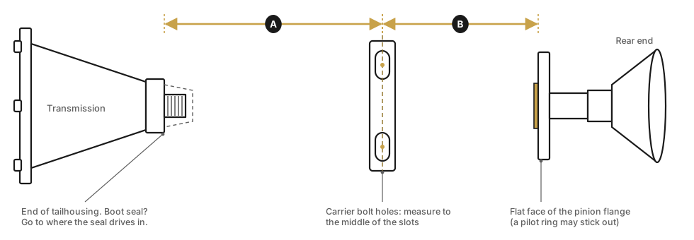
- A · Front length: From the end of the transmission tailhousing (where the seal seats) to the center of the carrier bearing bolt holes (middle of the slots).
- B · Rear length: From the center of the carrier bearing bolt holes (middle of the slots) to the flat face of the pinion flange.
M2-4
Two-piece: your slip yoke to pinion flange
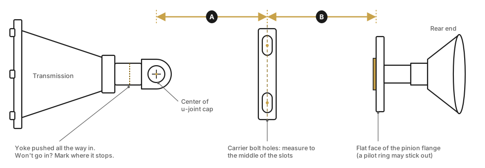
- A · Front length: From the center of the u-joint cap in your slip yoke, pushed all the way into the transmission to the center of the carrier bearing bolt holes (middle of the slots).
- B · Rear length: From the center of the carrier bearing bolt holes (middle of the slots) to the flat face of the pinion flange.
M2-5
Two-piece: bolt-on yokes at both ends
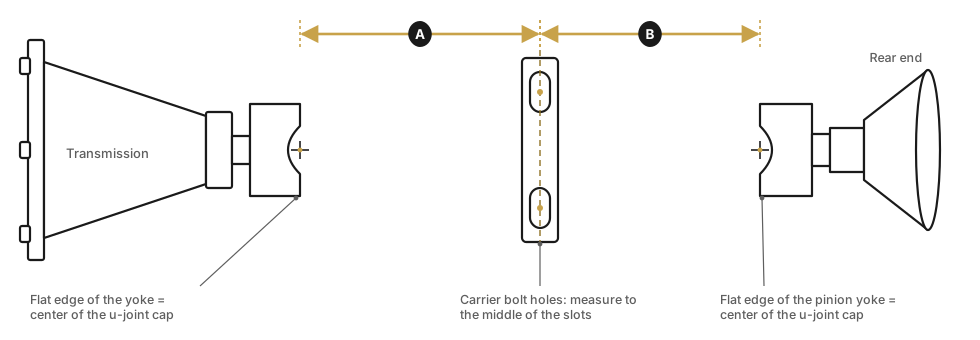
- A · Front length: From the flat edge of the transmission yoke (the centerline of the u-joint cap) to the center of the carrier bearing bolt holes (middle of the slots).
- B · Rear length: From the center of the carrier bearing bolt holes (middle of the slots) to the flat edge of the pinion yoke (the centerline of the u-joint cap).
M2-6
Two-piece: transmission flange to pinion flange
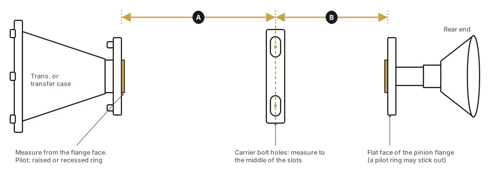
- A · Front length: From the face of the transmission or transfer case flange to the center of the carrier bearing bolt holes (middle of the slots).
- B · Rear length: From the center of the carrier bearing bolt holes (middle of the slots) to the flat face of the pinion flange.
M2-7
Two-piece: transmission flange to pinion yoke
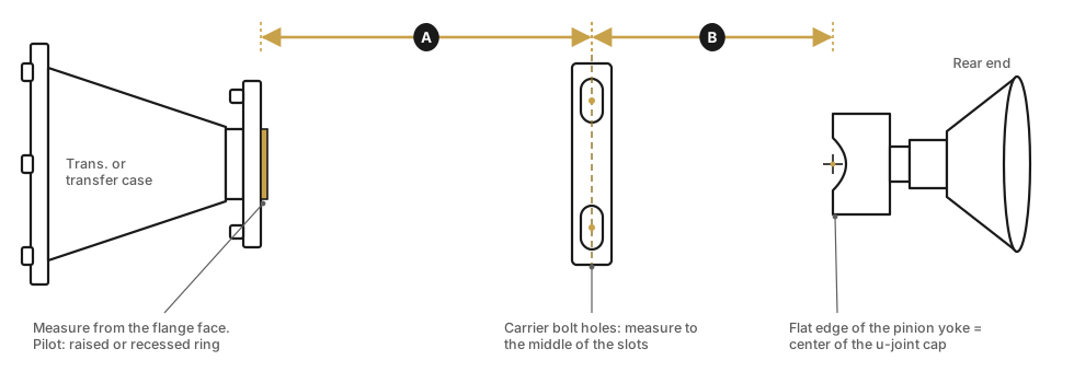
- A · Front length: From the face of the transmission or transfer case flange to the center of the carrier bearing bolt holes (middle of the slots).
- B · Rear length: From the center of the carrier bearing bolt holes (middle of the slots) to the flat edge of the pinion yoke (the centerline of the u-joint cap).
M2-8
Two-piece: early GM X-frame with inline carrier bearing
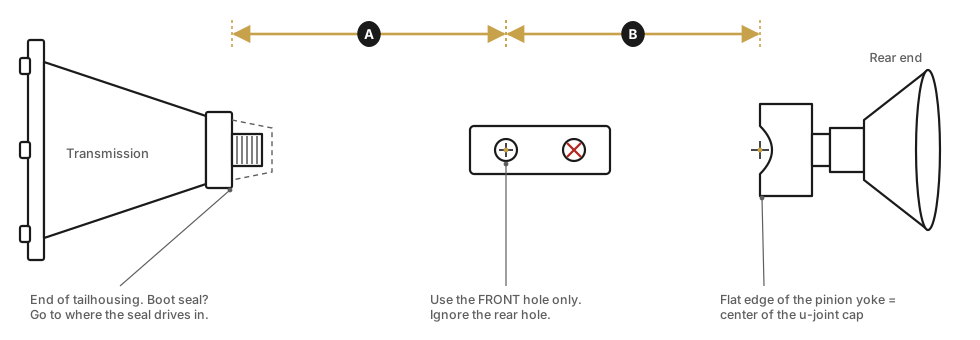
- A · Front length: From the end of the transmission tailhousing (where the seal seats) to the center of the FRONT hole in the inline carrier (ignore the rear hole).
- B · Rear length: From the center of the FRONT hole in the inline carrier (ignore the rear hole) to the flat edge of the pinion yoke (the centerline of the u-joint cap).
U-joint identification chart
Measure both ends of the shaft: they can be different series. Squeeze the joint together with the caps on, then measure the cap diameter (A) and the overall width across the caps (B). This chart is for outside snap-ring u-joints.
| Series | A · Cap diameter | B · Overall width |
|---|---|---|
| 1310 | 1-1/16" | 3-7/32" |
| 1310 big cap (Ford) | 1-1/8" | 3-7/32" |
| 1330 | 1-1/16" | 3-5/8" |
| 1330 big cap (Ford) | 1-1/8" | 3-5/8" |
| 1350 | 1-3/16" | 3-5/8" |
| 1410 | 1-3/16" | 4-3/16" |
| 1480 | 1-3/8" | 4-3/16" |
| 1550 | 1-3/8" | 4-31/32" |
The 1-1/8" "big cap" 1310 and 1330 joints are Ford-only. Inside snap-ring joints (GM 3R, 7260, 7290): measure the same way and text us a photo, and we'll confirm the series. Printable u-joint chart (PDF) · 1310 vs 1330 vs 1350 explained
Car apart? Bring the old shaft.
If the vehicle is torn down or you're doing an engine or transmission swap, we can use your old driveshaft as a template or work from your mockup. Call and we'll walk you through it.
Frequently asked questions
How accurate do my driveshaft measurements need to be?
Aim for within about 1/8 inch. If a measurement is borderline or you're unsure, call or text photos before ordering.
Can I measure with the vehicle on a lift?
Only on a drive-on lift with the weight on the suspension. If the axle hangs, the suspension droops and the length you measure will be wrong.
Can I just send my old driveshaft as a template?
Yes. If the old shaft was the correct length and nothing in the drivetrain has changed, bring it in and we'll measure it directly.
How do I find my u-joint series?
Measure the u-joint bearing cap diameter and the span across the caps with calipers, or text us a photo with a tape measure next to it. We'll identify the series for you.
- 1310 vs 1330 vs 1350: Sizes, strength and when to step up a series.
- Driveline & Pinion Angles: Operating angles, pinion angle and how to measure them right.
- Drivetrain vs Driveshaft: The terms, the parts, and FWD vs RWD vs AWD vs 4WD.